Signal Conditioning for RTD and Thermocouple
Signal Conditioning for RTD
Temperature Measurement: Measurement of temperature is critical in modern electronic devices. Knowledge of system temperature can also be used to control battery charging as well as prevent damage to expensive microprocessors. In modern days, we have Thermocouple, RTDs, Semiconductor based temperature sensors and thermistors for temperature measurement. Accurate temperature measurements are required in many systems such as process control and instrumentation applications. In most cases, because of low-level nonlinear outputs, the sensor output must be properly conditioned and amplified before further processing can occur.
Signal conditioning is an electronic circuit that manipulates a signal in a way that prepares it for the next stage of processing. Many data acquisition applications involve environmental or mechanical measurement from sensors, such as temperature and vibration.
Resistance Temperature Devices (RTDs) are accurate, but require excitation current and are generally used in bridge circuits. Thermistors have the most sensitivity but are the most non-linear. However, they are popular in portable applications such as measurement of battery temperature and other critical temperatures in a system.
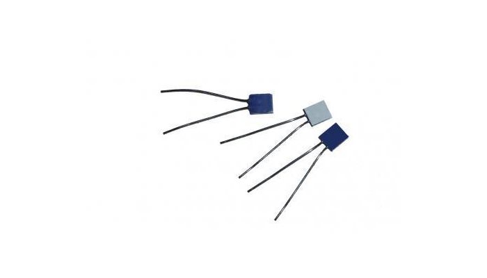
The RTD is a sensor whose resistance changes with temperature. It is typically built of a platinum (Pt) wire wrapped around a ceramic bobbin and exhibits behavior which is more accurate and more linear over wide temperature ranges than a thermocouple. Linearizing an RTD is less complex.
How Does an RTD Work?
"RTD" is an abbreviation for "Resistance Temperature Detector" An RTD is a type of temperature sensor which can be utilised in the manufacture of Variohms' temperature probe range.
They are available with different temperature / resistance values depending on the application requirement.
How Does an RTD Work?
An RTD consists of a resistance element and insulated copper wires. The most common number of wires is 2; however some RTDs have 3 or 4 wires. The resistive element is the temperature sensing element of the RTD. It is usually platinum because as a material it is highly stable over time, it has a wide temperature range, it offers an almost linear relationship between temperature and resistance and it has a chemical inertness. Nickle or copper are also other popular choices of material for the resistive element.
An RTD works by using a basic principle; as the temperature of a metal increases, so does the resistance to the flow of electricity. An electrical current is passed through the sensor, the resistance element is used to measure the resistance of the current being passed through it. As the temperature of the resistance element increases the electrical resistance also increases. The electrical resistance is measured in Ohms. The resistance value can then be converted into temperature based on the characteristics of the element. Typical response time for an RTD is between 0.5 and 5 seconds making them suitable to applications where an immediate response is not required.
Benefits of using RTD Temperature Sensors
RTDs are used within different industries including; automotive, white goods, marine and industrial applications. Benefits of using RTDs over other temperature sensors are;
· Highly accurate
· Consistent
· Offer long term stability
· High repeatability
· Suitable for extreme environments
· Have a high temperature range (depending on resistance element material)
Signal Conditioning for Thermocouple
A
thermocouple is a sensor that measures temperature. It consists of two
different types of metals, joined together at one end. When the junction of the
two metals is heated or cooled, a voltage is created that can be correlated
back to the temperature. A thermocouple is a simple, robust and cost-effective
temperature sensor used in a wide range of temperature measurement processes.
Working of
Thermocouple:
When
two wires composed of dissimilar metals are joined at both ends and one of the
ends is heated, there is a continuous current which flows in the thermoelectric
circuit.
If
this circuit is broken at the center, the net open circuit voltage i.e. the
Seebeck voltage is a function of the junction temperature and the composition
of the two metals. Which means that when the junction of the two metals is
heated or cooled a voltage is produced that can be correlated back to the
temperature.

Thermocouples require the following
signal conditioning:
Amplification for High-Resolution ADC:
Thermocouples
generate very low-voltage signals, usually measured in microvolts. To acquire
these signals with a measurement device, you must amplify the thermocouple
signal to measure it accurately with a standard 12-bit measurement device.
Alternatively, you can use a measurement device with a high-resolution ADC. A
device with 16 bits of resolution and amplification capabilities or a device
with 24 bits of resolution is recommended.
Cold-Junction Compensation:
Thermocouples
require some form of temperature reference to compensate for unwanted parasitic
thermocouples. A parasitic thermocouple is created when you connect a
thermocouple to an instrument. Because the terminals on the instrument are made
of a different material than the thermocouple wire, voltage is created at the
junctions, called cold junctions, which changes the voltage output by the
actual thermocouple.
Traditionally,
the temperature reference was 0 °C. The National Institute of Standards and
Technology (NIST) thermocouple reference tables are created using this setup.
Although an ice bath reference is quite accurate, it is not always practical. A
more practical approach is to measure the temperature of the reference junction
with a direct-reading temperature sensor, such as a thermistor or an IC sensor,
and then subtract the parasitic thermocouple thermoelectric contributions. This
process is called cold-junction compensation.
Filtering:
A
thermocouple can act much like an antenna, making it very susceptible to noise
from nearby 50/60 Hz power sources. Therefore, apply a 2 Hz or 4 Hz low pass
filter to your thermocouple signal to remove power line noise.
Linearization:
After
setting up the equivalent ice point reference EMF in either hardware or
software, the measured thermocouple output must be converted to a temperature
reading. The output is proportional to the temperature of the TC junction, but
is not perfectly linear over a very wide range. The standard way to obtain high
conversion accuracy for any temperature uses the value of the measured
thermocouple voltage plugged into a characteristic equation for that particular
type of thermocouple. The output voltage of a thermocouple is not linear with
temperature. Therefore, the system must perform linearization either through
hardware or software.
Thermocouple
signal conditioning is more complex than that of other temperature-measurement
systems. Modern INA architectures and
the advancement of silicon-based IC temperature sensors have addressed many of
the historical design challenges associated with thermocouples. Several
silicon-IC manufactures have integrated many analog, mixed-signal and
temperature-sensing devices for CJC,
further minimizing design efforts while improving overall system performance.


Comments
Post a Comment